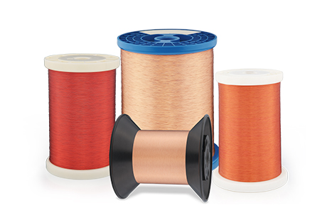
Note: This article discusses the material selection, application boundaries, and failure mechanisms of enamelled copper wire. It does not cover enamel formulation, coating passes, furnace temperature, line speed, or curing windows. The term “tens of microns” is used to indicate a common scale range. Actual enamel film build varies depending on wire diameter, insulation class, round or rectangular wire structure, and standard specifications.
When a motor burns out, the copper wire overheating is often the first suspected cause. When a transformer experiences a short circuit, people usually first check the conductor cross-sectional area and winding temperature rise. However, in many low-voltage motors, compressors, relays, transformers, and new energy vehicle drive motors, the component that actually separates adjacent turns of wire is often only an organic insulating enamel film with a thickness ranging from microns to tens of microns.
This thin enamel film contributes almost no electrical conductivity, yet it must simultaneously withstand winding bending, slot abrasion, impregnation resin, refrigerants or oils, long-term temperature rise, PWM pulse voltage, and partial discharge. As long as the copper core remains intact, it can still conduct electricity; but once the enamel film develops a pinhole, crack, or electrical aging path at a single point, adjacent turns may evolve from a localized short circuit into complete winding failure.
IEC 60317 and NEMA MW 1000 do not define enamelled wire simply as “copper wire coated with paint.” Instead, they evaluate finished wire products through multiple aspects, including dimensions, enamel build-up, breakdown voltage, pinholes, flexibility, adhesion, heat shock resistance, softening breakdown, solvent resistance, and solderability [1-9]. This demonstrates that the core value of high-end enamelled wire is not whether the enamel surface appears smooth and glossy, but whether the insulation function remains stable throughout the entire coil of wire.
Enamelled copper wire is not sold as “copper + a layer of coating,” but as the probability that millions of turn-to-turn contacts per unit length will continue operating without failure.
1. Where Is Enamelled Copper Wire Used? It Is Far More Than Just Motor Winding Wire
Enamelled wire, also known as winding wire or magnet wire, is designed to wind conductors into coils with high numbers of turns and high slot fill factors while maintaining the smallest possible insulation thickness. Compared with ordinary plastic-insulated wires, which generally have thicker insulation layers and are mainly used for connection and power supply, enamelled wire focuses on thin insulation, high filling efficiency, and excellent winding capability.
| Application | Typical Products | Why Use Enameled Wire | Key Issues to Focus On |
|---|
| Household appliances & small motors | Fans, washing machines, water pumps, vacuum cleaners, power tools | Round-wire random winding; balance of cost and windability | Pinholes, winding scratches, temperature rise, and impregnation compatibility |
| Refrigeration compressors | Air conditioners, refrigerators, heat-pump compressors | Long-term thermal load + contact with refrigerant and refrigeration oil | Refrigerant resistance, oil resistance, sealing-system life |
| Industrial motors & generators | Pumps, fans, machine tools, industrial drives | Continuous operation, vibration, thermal cycling | Thermal class, mechanical wear, insulation-system matching |
| Transformers & inductors | Power transformers, chargers, inverters, inductors | High turns count, low loss, size-constrained | Solderability, inter-turn voltage, high-frequency losses |
| Relays & solenoid valves | Relays, contactors, solenoids, actuators | Fine wire diameter, high turns count, small coil volume | Wire-diameter consistency, wire breakage, insulation pinholes |
| Traditional automotive electrical | Starters, generators, electric power steering, oil pumps | Vibration, temperature variation, and batch consistency | Mechanical damage, thermal aging, chemical media |
| New-energy vehicle drive motors | Round-wire windings, Hairpin flat-wire windings | High slot-fill factor, high power density, inverter supply | Corner field strength, PWM pulses, partial discharge, forming damage |
| High-frequency power electronics | High-frequency transformers, filter inductors, wireless charging coils | High frequency; significant skin and proximity effects | Dielectric loss, heat resistance, winding and termination |
Although these products are all called enamelled copper wire, their required material systems are not identical. For small coils operating at low temperatures and requiring direct soldering, polyurethane enamel coatings are often selected due to their solderability. High-temperature motors commonly use polyesterimide, polyamide-imide, or double-layer composite enamel systems. New energy vehicle drive motors must additionally address risks caused by high-frequency PWM pulses and partial discharge [2-8,10-13].
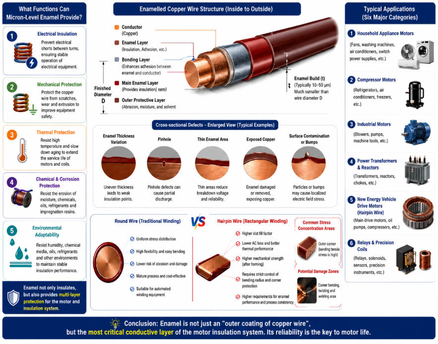
2. Why Can the Enamel Film Be So Thin, Yet Cannot Be Reduced Indefinitely?
The economic value of enamelled wire comes from being “thin.” A thinner insulation layer allows more copper to be placed within the same slot space, increasing the slot fill factor, reducing winding resistance and copper loss, and enabling more compact motor or transformer designs.
However, enamel film is not an ideal cylindrical layer with perfectly uniform thickness and zero defects. Surface scratches on copper wire, enamel flow behavior, curing shrinkage, die eccentricity, and fluctuations during multi-pass coating can all create localized thin areas. For insulation performance, meeting the average thickness requirement does not guarantee that the minimum local thickness is sufficient; the thinnest point often determines the occurrence of pinholes, breakdown, and partial discharge initiation.
Therefore, IEC 60317 specifies enamel build-up, finished wire dimensions, and requirements for pinholes, breakdown voltage, flexibility, and adhesion according to different wire diameters and insulation classes [1]. Increasing enamel thickness can improve electrical safety margins, but it reduces slot fill factor, increases final wire diameter, and raises the tensile strain on the outer layer during bending.
The essence of enamel thickness is not “the thicker the insulation, the safer,” but rather the balance between copper fill rate, electrical margin, bending strain, and manufacturing consistency.
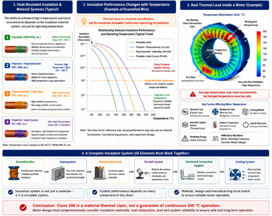
3. Thermal Class 200 Does Not Mean the Motor Can Continuously Operate at 200°C
One of the most common misunderstandings about enamelled wire is interpreting “Class 155, 180, 200, 220, or 240” as the maximum continuous operating temperature allowed for the motor.
IEC 60317 defines temperature indexes and heat shock requirements for different enamelled wire categories. For example, solderable polyurethane enamelled round copper wire may correspond to Class 155, polyesterimide systems may reach Class 180 or 200, while polyamide-imide systems can achieve Class 220 or 240 [2-7].
However, the temperature index is based on long-term thermal life evaluation under specified testing methods. It does not represent the recommended continuous winding hotspot temperature after installation in a specific motor. Actual service life is also affected by oxygen, humidity, refrigerants, impregnation resin, mechanical stress, voltage waveform, partial discharge, and cooling conditions.
IEC 60034-18-1 also emphasizes that the complete electrical insulation system should be evaluated rather than judging performance based only on the thermal class of a single material [10].
Thermal aging causes oxidation, polymer chain breakage, cross-linking changes, and loss of volatile components. Macroscopically, this appears as enamel hardening, embrittlement, cracking, and changes in dielectric loss and breakdown performance. Accelerated thermal aging studies have shown that insulation resistance, partial discharge inception voltage, and dielectric parameters change systematically during aging processes [17-22].
| Insulation System | Main Advantages | Limitations That Cannot Be Ignored | More Common Applications |
|---|
| Polyurethane (PU) | Good solderability and easy processing | Relatively limited thermal class and overload resistance | Small transformers, relays, electronic coils |
| Polyester / Polyesterimide (PE/PEI) | Balanced overall performance and cost | High-temperature hydrolysis, thermal aging, and mechanical performance need to be properly matched | Household appliance motors, general industrial motors |
| PEI + PAI Double-Layer System | Base insulation layer with outer layer providing abrasion resistance and heat resistance | Requires strict control of composite interfaces, curing process, and consistency of each layer | High-grade motors, automotive motors, rectangular wire applications |
| Polyamide-Imide (PAI) | Excellent heat resistance, adhesion, and abrasion resistance | Higher cost, processing challenges, and compatibility issues with specific chemical media | High-temperature motors, inverter-driven motors |
| Polyimide (PI) | Outstanding high-temperature performance and dielectric properties | High cost and difficulty balancing processing performance and flexibility | Aerospace, high-temperature, and special electromagnetic coils |
| Nano-Composite Corona-Resistant System | Potential improvement in partial discharge and pulse endurance | Requires simultaneous control of filler dispersion, interfaces, and mechanical properties | SiC inverter systems, high-voltage drive motors |
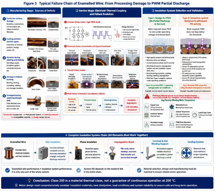
4. Why Can Enamelled Wire Fail After Passing Factory Inspection but After Being Wound Into a Motor?
The inspection samples of enamelled wire are usually straight samples or specified twisted specimens, while actual manufacturing processes subject the wire to repeated bending, tensioning, slot insertion, shaping, welding, and impregnation.
A wire with no pinholes at shipment does not necessarily remain intact after winding and assembly.
1. Random Winding with Round Wire: Cross Points and Slot Openings Are the Most Dangerous Areas
In random winding, wire turns cross each other, and contact points experience local pressure. When coils are inserted into stator slots, slot edges, insulation paper edges, and guiding tools may scratch the enamel layer.
A small surface scratch that is barely visible may simultaneously reduce enamel thickness, adhesion, and breakdown voltage.
2. Rectangular Magnet Wire and Hairpin: Edges and Forming Areas Are the Most Critical
Rectangular conductors improve slot fill factor, but during bending, the enamel film on the outer radius experiences greater tensile stress, while the inner side may experience compression and wrinkling. Twisting, expanding, and welding areas also undergo complex three-dimensional deformation.
IEC 60317-93 and other standards specifically define requirements for Class 220 double-layer enamelled rectangular copper wire [8]. However, qualified standard wire cannot replace cross-sectional and electrical verification after forming.
3. Impregnation Does Not Necessarily Repair All Enamel Defects
Impregnation resin can secure the winding, improve heat transfer, and fill some gaps. However, for through scratches, exposed copper, or high-field defects, resin cannot always restore the original turn insulation performance.
There are also issues related to swelling, stress, and compatibility between impregnation materials and enamel films [10,18-19].
5. Why Do New Energy Vehicle Motors Amplify Enamelled Wire Challenges?
Traditional frequency-powered motors experience relatively slow turn-to-turn voltage changes, while inverter-driven motors are exposed to repeated steep voltage pulses.
SiC devices can improve system efficiency and power density due to their high switching speed, but they may also introduce higher dv/dt, reflected overvoltage at terminals, and more uneven turn-to-turn voltage distribution. Research shows that PWM waveform characteristics, cable length, pulse rise time, and overvoltage behavior can change the partial discharge behavior of twisted enamelled wire pairs [14-16].
Partial discharge does not immediately break down the enamel film. Instead, repeated micro-discharges occur in air gaps, cracks, and contact edges, gradually eroding the insulation surface and eventually forming electrical treeing or penetrating channels. Thermal aging further reduces partial discharge inception voltage, causing voltage waveforms that were originally safe to enter a dangerous range later in service life [21-22].
IEC 60034-18-41 applies to Type I insulation systems expected to remain free of partial discharge during operation, while IEC 60034-18-42 applies to Type II insulation systems designed to withstand partial discharge activity [11-12]. This distinction shows that using corona resistant magnet wire alone cannot solve all problems. Motor winding structure, inverter output, cables, terminal overvoltage, impregnation, and manufacturing defects must be considered together.
In inverter-driven motors, enamelled wire is not an isolated material, but the most vulnerable interface influenced jointly by power devices, cables, winding topology, and the insulation system.
6. Is Adding Nanoparticles Enough for Corona-Resistant Enamelled Wire?
Introducing inorganic nanoparticles such as SiO₂ and Al₂O₃ into polymer enamel films can improve thermal performance and partial discharge resistance by modifying local electric fields, heat transfer, and discharge erosion paths. Existing studies have reported that properly dispersed surface-modified silica in enamel films can improve thermal stability and breakdown strength [20,23].
However, more nanoparticle content is not always better. Particle agglomeration may create electric field concentration and mechanical defects. Excessive polymer-particle interfaces may increase moisture sensitivity. Fillers may also reduce enamel flexibility and adhesion. For Hairpin rectangular wire, improving partial discharge resistance while causing cracking after bending cannot be considered reliable performance.
Therefore, evaluating corona-resistant enamelled wire requires comprehensive consideration of partial discharge life, breakdown voltage, adhesion, scratching resistance, bending performance, heat shock resistance, and post-forming defects, rather than simply comparing pulse endurance time.
7. The Most Common Failure Modes of Enamelled Wire Are Usually Not Caused by a Single Factor
| Failure Mode | Main Causes | Final Effects |
|---|
| Pinholes or Local Thin Areas | Uneven coating, substrate scratches, dust contamination, or curing defects | Local breakdown; weak points may still form after impregnation |
| Insufficient Adhesion | Poor copper surface cleaning, phosphate treatment issues, or mismatch in curing conditions | Enamel peeling or copper exposure after bending and abrasion |
| Thermal Aging Degradation | Long-term hotspots, overload, oxidation, and polymer chain breakage | Enamel hardening, micro-cracks, and reduced breakdown voltage |
| Mechanical Damage | Winding guides, slot edges, crossover pressure, and forming stress | Reduced local insulation thickness and increased risk of turn-to-turn short circuits |
| Partial Discharge Erosion | PWM pulses, electrical stress, and high electric field concentration at edges | Surface erosion pits, electrical treeing, and eventual breakdown |
| Chemical Incompatibility | Refrigerants, oils, impregnation resins, cleaning agents, or moisture exposure | Swelling, cracking, and changes in dielectric and adhesion properties |
| Welding / Stripping Damage | Laser stripping, mechanical stripping, or heat-affected zones | Terminal short circuits, carbon residues, and defects in welding-affected areas |
| Insufficient Batch Consistency | Variations in outer diameter, enamel thickness, pinholes, and curing conditions | Fluctuations in automatic winding tension and precision assembly, resulting in lower yield |
8. Purchasing Enamelled Copper Wire Cannot Be Limited to “Wire Diameter + Temperature Class”
A purchase specification that only states “φ0.50 mm, Class 180 enamelled copper wire” cannot define a high-reliability product.
At minimum, the following requirements should be specified:
Conductor shape, copper material grade, dimensional tolerance, and resistance requirements;
Round or rectangular wire insulation system, single-layer/double-layer structure, and insulation class;
Enamel build-up grade, maximum finished diameter, and minimum local insulation margin;
Requirements for breakdown voltage, pinholes, flexibility, adhesion, abrasion resistance, and heat shock;
Whether solderability, direct soldering temperature range, or specific stripping methods are required;
Whether the wire contacts refrigerants, lubricating oils, impregnation resins, cleaning agents, or humid environments;
Whether it is used for inverter-driven motors and requires PDIV, pulse life, or partial discharge resistance evaluation;
Whether rectangular wire requires cross-sectional and electrical performance verification after Hairpin forming, twisting, and welding;
Coil length, number of joints, winding arrangement, packaging, batch traceability, and online defect records.
For high-end motors, qualified bare wire is only the first threshold. More valuable data is whether the insulation can maintain sufficient margin after experiencing the customer’s actual winding tension, minimum bending radius, slot assembly, impregnation process, and thermal cycling.
9. Conclusion: Copper Core Delivers Electricity, Enamel Film Ensures Electricity Travels Only Where It Should
Enamelled copper wire appears to be nothing more than copper wire covered with an insulating coating. However, this thin layer exists at the smallest distance between adjacent turns, the first interface exposed to slot friction, the forefront of hotspot and refrigerant contact, and the area with the highest concentration of PWM electric fields.
It must be thin enough to improve slot fill factor, yet thick and uniform enough to withstand electrical breakdown. It must resist heat without becoming brittle after aging. It must maintain strong adhesion while remaining flexible during bending. It must also work together with impregnation resin, refrigerants, welding processes, and inverter waveforms.
Therefore, evaluating enamelled copper wire should not only ask “what is the temperature class?” but also: What type of resin system is used? Is it round wire or rectangular wire? How much insulation margin remains at the thinnest point after winding and forming? Does partial discharge occur under actual PWM rise times and cable lengths? How does PDIV change after thermal aging? Will impregnation materials and chemical environments affect the enamel film?
The true value of high-end enamelled copper wire is not achieving an extremely high initial breakdown voltage, but maintaining reliability after hundreds of thousands of bending cycles, thousands of hours of thermal exposure, and hundreds of millions of pulses—without allowing a tiny defect to develop into failure of the entire motor.
References and Standards
The following materials are used to support discussions on enamelled wire classification, thermal grades, winding insulation systems, partial discharge, thermal aging, and nano-composite enamel films. Actual procurement and certification should follow official standards and customer technical agreements.
[1] IEC 60317-0-1:2013+AMD1:2019 CSV, Specifications for particular types of winding wires – Part 0-1: General requirements – Enamelled round copper wire.
[2] IEC 60317-20:2013+AMD1:2019 CSV, Solderable polyurethane enamelled round copper wire, class 155.
[3] IEC 60317-23:2013, Solderable polyesterimide enamelled round copper wire, class 180.
[4] IEC 60317-84:2021, Polyesterimide enamelled round copper winding wires, class 200.
[5] IEC 60317-13:2010+AMD1:2024, Polyester or polyesterimide overcoated with polyamide-imide enamelled round copper wire, class 200.
[6] IEC 60317-57:2010+AMD1:2024 CSV, Polyamide-imide enamelled round copper winding wire, class 220.
[7] IEC 60317-59:2015+AMD1:2024 CSV, Polyamide-imide enamelled round copper wire, class 240.
[8] IEC 60317-93:2023, Polyester or polyesterimide overcoated with polyamide-imide enamelled rectangular copper wire, class 220.
[9] ANSI/NEMA MW 1000-2020, Magnet Wire. National Electrical Manufacturers Association.
[10] IEC 60034-18-1:2022, Rotating electrical machines – Part 18-1: Functional evaluation of insulation systems – General guidelines.
[11] IEC 60034-18-41:2014+AMD1:2019 CSV, Partial discharge free electrical insulation systems (Type I) used in rotating electrical machines fed from voltage converters.
[12] IEC 60034-18-42:2017+AMD1:2020, Partial discharge resistant electrical insulation systems (Type II) used in rotating electrical machines fed from voltage converters.
[13] IEC TS 60034-25:2022, AC electrical machines used in power drive systems – Application guide.
[14] Hayakawa N, Inano H, Inuzuka K, Morikawa M, Okubo H. Partial Discharge Propagation and Degradation Characteristics of Magnet Wire for Inverter-Fed Motor under Surge Voltage Application. IEEE CEIDP, 2006. doi:10.1109/CEIDP.2006.311995.
[15] Hayakawa N, Shimizu F, Peng X, Okubo H. Partial Discharge Inception Voltage for Magnet Wire of Inverter-Fed Motors under Surge Voltage Application. IEEE CEIDP, 2010. doi:10.1109/CEIDP.2010.5723994.
[16] Diab M, Zhou W, Yuan X. Impact of PWM Voltage Waveforms on Magnet Wire Insulation Partial Discharge in SiC-Based Motor Drives. IEEE Access, 2021, 9:156599-156612. doi:10.1109/ACCESS.2021.3129266.
[17] Khowja M R, Turabee G, Giangrande P, et al. Lifetime Estimation of Enameled Wires Under Accelerated Thermal Aging Using Curve Fitting Methods. IEEE Access, 2021, 9:18993-19003. doi:10.1109/ACCESS.2021.3052058.
[18] Pereira dos Santos Lima G, Ait-Amar S, Velu G, et al. Performance Analysis Based on Thermal Aging Tests of Sol-Gel and Polymer Insulated Wires by Enameling and Extrusion Technology. Energies, 2022, 15:5164. doi:10.3390/en15145164.
[19] Pereira dos Santos Lima G, Ait-Amar S, Velu G, et al. Thermal Evaluation of Silica-Based Insulated Magnet Wires from the Sol-Gel Process. Gels, 2023, 9:619. doi:10.3390/gels9080619.
[20] Kim Y, Park S Y, Kwon S Y, et al. Enhanced Thermal Resistance of Nanocomposite Enameled Wire Prepared from Surface Modified Silica Nanoparticle. Thermochimica Acta, 2012, 542:62-68. doi:10.1016/j.tca.2011.12.005.
[21] Zhang Z, Wu Z, Zhang H, Cheng Y, Ren H. Analysis of Influence of Insulating Resin Paint Film on Enameled Wire Properties Based on Molecular Simulation. Coatings, 2022, 12:1352. doi:10.3390/coatings12091352.
[22] Khan I, Guastavino F, Della Giovanna L, Torello E. Partial Discharge Inception Voltage Monitoring of Enameled Wires under Thermal Stress over Time. Energies, 2024, 17:4578. doi:10.3390/en17184578.
[23] Höpner V N, Wilhelm V E. Insulation Life Span of Low-Voltage Electric Motors—A Survey. Energies, 2021, 14:1738. doi:10.3390/en14061738.
[24] Kikuchi Y, Miyamae M, Fukuda Y, et al. Partial Discharge Characteristics of Twisted Enameled Magnet Wires for Inverter-Fed Random Wound Motors. ISEIM, 2011:125-127. doi:10.1109/ISEIM.2011.6826365.

 English
 한국어
한국어 français
 Deutsch
 Español
 italiano
 العربية
 tiếng việt
 Türkçe
 ไทย
ไทย 中文
中文